
Heat exchangers are technical devices designed to transfer heat from one medium to another.
Brief overview of heat exchange equipment
Depending on the method of heat transfer, there are two main groups of heat exchangers:
1) surface heat exchangers, in which heat transfer between media occurs through the surfaces separating them – a blind wall;
2) mixing heat exchangers, in which heat is transferred from one medium to another through their direct contact.
Much less frequently used in industry are regenerative heat exchangers, in which the heating of liquid media occurs when hot and cold heat carriers contact the same surface alternately. Heat accumulates in the wall upon contact with the hot heat carrier and is released upon contact with the cold one.
Today, surface heat exchangers are the most common heat exchange equipment. The following designs of surface heat exchangers can be distinguished: shell-and-tube heat exchanger, “pipe in pipe” type, submersible, plate heat exchangers, spiral, etc.
Designs and types of surface heat exchangers
Heat exchangers play an important role in various industrial and domestic systems, ensuring efficient heat transfer between two environments. They are used in heating, cooling, ventilation and other processes where temperature control is required.
Knowing the different designs and types of heat exchangers allows you to choose the most suitable option for specific tasks. The design and features of each type play a key role in the efficiency and reliability of the equipment.
Shell and tube heat exchangers
A tubular heat exchanger (Fig. 1) consists of a bundle of tubes placed in a cylindrical body 1 (casing). The body of a shell-and-tube heat exchanger is a tube welded from one or more steel sheets. The thickness of the wall of the casing (casing) is determined by the pressure of the working medium and the diameter of the casing, but in practice no less than 4 mm is used. Flanges are welded to the cylindrical edges of the casing. The supports of the device are attached to the outer surface of the casing. The space between the tubes 3 and the side surface of the casing is called the intertube space. The tubes are rolled (fastened) or welded to the tube sheets 2. The cover and bottom 5 are attached to the flanges of the casing, on which are located branches 4 for the supply and discharge of the heated medium HC. On the casing there are also branches 4 for the supply and discharge of the cooled medium OS (in the figure, the cooled medium is steam).
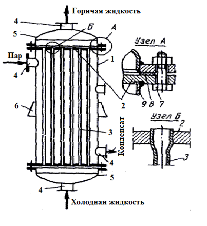
Fig.1 Shell and tube heat exchanger
1- body; 2- tube grid; 3- heating pipe; 4- branch pipe; 5- bottoms; 6- supports; 7- bolt; 8- gasket; 9- shell.
The tubes usually have a diameter of d ≥ 10 mm and are made of materials that conduct heat well (brass, copper, carbon steel, stainless steel). A major disadvantage of single-pass heat exchangers is the discrepancy between the throughput of the tube bundle and the heat exchange area. For example, a tube with a diameter of 20 mm (at a flow rate of 1 m / sec) can pass about 1.0 t / h of liquid; while the surface area of the tube with a normal length of 3.5 m is only about 0.2 m2. This area will not be enough to significantly heat such a large amount of liquid. This disadvantage can be eliminated by grouping the tubes into separate bundles (passages) and installing appropriate partitions. In this case, we achieve the effect due to the increase in the flow path several times. Such a heat exchanger is called a multi-pass (Fig. 2a). Here, the working fluid passes through the tube space in several passes, flowing sequentially through all the tube bundles.
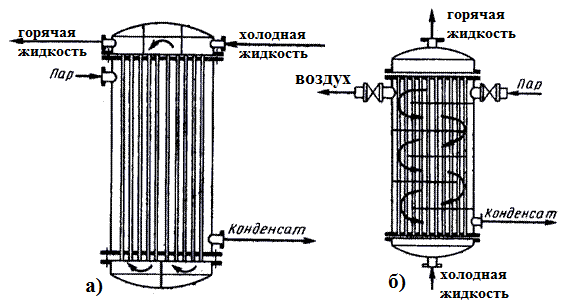
Fig.2 Diagram of a multi-pass tubular heat exchanger:
a) by the pipe space; b) by the interpipe space
With a small number of passes (two or three), the partitions are made along the chords, with a large number – radially or concentrically. Structurally, it is more convenient to arrange an even number of passes, usually no more than 16. If the coolant in the inter-pipe space is liquid, then to increase its speed, partitions are also arranged – longitudinal and transverse (for steam, only a single-pass design is used). Longitudinal partitions divide the inter-pipe space into the same number of passes as the pipe space has. These partitions ensure the principle of counter-flow of working fluids. The partitions are installed parallel to the tubes and do not reach the opposite tube sheet. A large number of partitions is not recommended due to the difficulty of sealing their joints with the tube sheets.
Transverse partitions are either overlapping or non-overlapping. Overlapping partitions cross the entire intertube space, leaving an annular gap of about 2 mm wide around each tube. The distance between the partitions is usually 100 mm. The working fluid flows through the annular gaps at high speed. In this case, turbulent eddies are formed in the gaps between the partitions, which leads to an increase in the heat transfer coefficient. Such partitions are not applicable if liquids can release sediment, since narrow gaps are easily clogged with it. Non-overlapping partitions (Fig. 2b) are made, for example, with a passage in the form of a sector or segment.
U-tube heat exchanger
A two-pass heat exchanger is often made with U-shaped tubes, the open ends of which are rolled into the same tube sheet (Fig. 3). When starting up heat exchangers, it is necessary to pay attention to the direction of movement of the working bodies. The hot (cooled) liquid should go down (feed from above), and the cold (heated) liquid should go up. In this case, we get a counter-current, which provides better thermal shear.
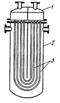
Fig.3. Diagram of a heat exchanger with U-shaped tubes
1- cover; 2- body; 3- U-shaped tubes
Tubular heat exchangers have found wide application in steam systems with temperatures of media above 200 degrees and pressure above 25 atmospheres. In all other cases, it is advisable to use plate heat exchangers, as they will be cheaper, take up less space and are easy to operate.
Heat exchangers “pipe in pipe”
Heat exchangers “pipe in pipe” are used at low flow rates of working fluids and high pressures. They are assembled from several series-connected elements formed by two concentrically located pipes (Fig. 4). Each element consists of 2 pipes inserted one into the other. The elements are connected in a battery in series, parallel or combined. In this case, pipes are connected to pipes, and annular spaces to annular spaces. The advantage of such heat exchangers is the observance of counterflow, which ensures the most complete use of the coolant. They allow achieving fairly high liquid velocities in the range of 1-1.5 m / s, which reduces the possibility of contaminant deposition on the heat exchange surface and increases the values of heat transfer coefficients. Note that these heat exchangers are more bulky, compared to shell-and-tube ones, and require a higher metal consumption per unit of heat exchange surface.
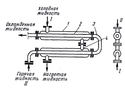
Fig.4 Heat exchanger of the “pipe in pipe” type
1- outer pipe; 2- inner pipe; 3- elbow; 4- branch pipe
Pipe-in-pipe heat exchangers are obsolete and are used extremely rarely.
Spiral heat exchangers
A spiral heat exchanger is a device in which the heating surface is formed by two thin metal sheets welded to a dividing partition and rolled into spirals.
Spiral heat exchangers consist of two rectangular spiral channels formed by metal sheets (Fig. 5), which serve as heat exchange surfaces. The inner ends of the spirals are connected by a partition. The channels are closed with covers at the ends and sealed with gaskets. At the outer ends of the channels there are pipes for the inlet and outlet of the heat carriers, two other pipes are welded to the flat side covers.
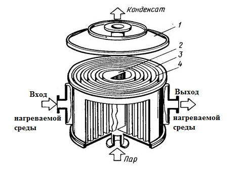

Fig.5. Spiral heat exchanger:
1 — cover; 2 — partition; 3,4 — metal sheets
A spiral heat exchanger is used for heat exchange between liquids and gases. These heat exchangers do not become clogged with solid particles suspended in heat carriers, so they are used for heat exchange between liquids with suspended particles, for example, for cooling mash in distilleries.
Operating principle: the heating medium is fed into the input manifold located on the casing, passes through the spiral channel and exits from the branch pipe located on the core of the device. The heated medium enters the branch pipe located on the core of the device from the opposite end of the spiral, passes through its spiral channel and exits from the output manifold of the heated medium.
Spiral heat exchangers are compact in comparison with tubular heat exchangers, and allow heat transfer at high heat carrier velocities with high heat transfer coefficients. The hydraulic resistance of spiral heat exchangers is lower than the resistance of multi-pass tubular devices at the same heat carrier velocities.
The disadvantage of spiral heat exchangers is the complexity of manufacturing, repair and cleaning. This leads to two main disadvantages: spiral heat exchangers are very expensive and their operation is the most labor-intensive of all heat exchange equipment. Spiral heat exchangers are seriously competing with heat exchangers Free Flow.
Plate heat exchangers
Plate heat exchangers (Fig. 6) are mounted on a frame consisting of upper and lower guides that connect the rack with a fixed plate. The movable plate moves along the guide beams. Between the movable and fixed plates there is a pack of steel stamped corrugated plates, which have channels for the passage of heat carriers, pulled together with tie rods. Sealing of the plates is achieved with the help of gaskets located in a special groove of the plate. Heat exchanger seals can withstand high operating pressures (up to 25 bar). Heat carriers to the channels formed by the plates pass through alternating channels through holes separated by gaskets.
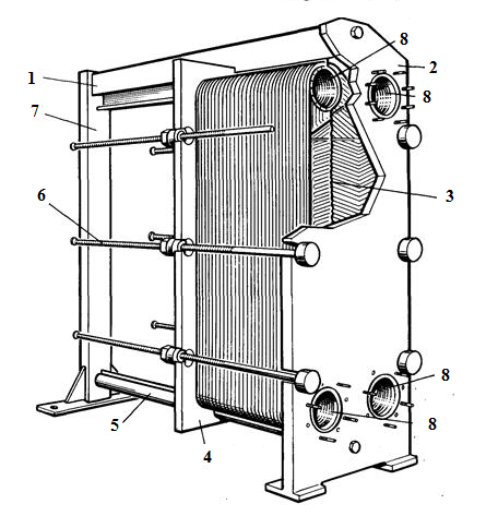
Fig.6. Plate heat exchanger
1- upper guide; 2- fixed plate; 3- heat transfer plate pack; 4- movable plate; 5- lower guide; 6- tie rod; 7- stand; 8- collector holes
Heat transfer in a plate heat exchanger most often occurs in counter-current, when the media move in different directions.
Plate heat exchangers (PHE) are used as heaters, coolers, heat recuperators. PHEs are compact and have a large heat transfer surface area, which is achieved by corrugating the plates. Plate heat exchangers can be disassemblable or non-disassemblable.
High efficiency is due to the high ratio of heat transfer surface area to heat exchanger volume due to high heat carrier velocities, as well as turbulence of flows by corrugated plate surfaces and low thermal resistance of plate walls.
The disadvantages of plate heat exchangers include the complexity of manufacturing, the possibility of clogging the plate surfaces with solid particles suspended in the liquid. Free Flow heat exchangers supplied by Teplo-Polis easily cope with the task of transferring heat between viscous media and media containing fibers and inclusions.
Comparison of heat exchangers
Each heat exchanger is in demand in its segment and has found its niche in a wide range of industries and technological processes. Let’s look at the unique features of each and determine the most optimal heat exchanger option.
Comparison of plate heat exchangers with shell and tube heat exchangers
- he heat transfer coefficient in plate heat exchangers is 3-4 times higher than in shell-and-tube heat exchangers, due to the special corrugated profile of the plate flow section, which ensures a high degree of turbulence of the heat carrier flows. Accordingly, the heat-transfer surface area of heat exchangers is 3-4 times smaller than that of shell-and-tube heat exchangers. As a result, plate heat exchangers have low metal consumption, are cheaper in price, and are compact (they can be installed in a small room).
- High maintainability:
- Unlike shell-and-tube heat exchangers, plate heat exchangers are easy to disassemble and clean quickly. This does not require dismantling the supply pipelines (in the case of using a single-pass heat exchanger);
- In a detachable plate heat exchanger, seals or plates can be quickly and easily replaced, and it is also possible to increase the heat exchange surface when increasing the thermal power;
- Plate heat exchangers are assembled from individual plates, the heating surface of which, as a rule, does not exceed 2 m2. This circumstance, combined with the optimally selected plate type, allows you to accurately, without excess, select the heat-transfer surface of the heat exchanger.
- The service life of the first failing unit of the sealing gasket reaches 10 years. The service life of heat exchange plates is 15-20 years. The cost of replacing seals from the cost of the PTO fluctuates within 15-25%, which is more economical than a similar process of replacing a brass pipe group in a KTTO, which is 80-90% of the cost of the device.
- The cost of installing a PTO is an order of magnitude lower than that of a shell-and-tube heat exchanger.
- A coolant with a lower temperature in heat supply systems allows heating water in the PTO to the required temperature.
- Individual calculation of each PTO according to the original program of the Manufacturer – allows to select its configuration in accordance with the hydraulic and temperature modes on both circuits. The calculation is made within 1-2 hours.
- Flexibility: If required, the heat transfer surface area of a plate heat exchanger can be easily increased by simply adding plates as needed.
- A two-stage hot water supply system, implemented in one heat exchanger, allows for significant savings on installation and a reduction in the required area for an individual heating point.
- The plate heat exchanger does not require special thermal insulation, since it has a relatively small internal volume.
- Plate heat exchangers are resistant to vibration, but tubular heat exchangers are not.
Comparative technical characteristics of shell-and-tube (S&T) and plate-type (PTO) heat exchangers of the same capacity
| Characteristic | WHO | PTO |
| Heat transfer coefficient (conditional) | 1 | 3 – 5 |
| The difference (possible) between the temperatures of the coolant and the heated medium at the outlet | Not less than 5-10 °C | 1 – 2 °С |
| Change in heat exchange surface area | Impossible | Allowed, multiple of the number of plates |
| Connection during assembly | Welding, rolling | Detachable |
| Accessibility for internal inspection and cleaning | Non-disassemblable, difficult to access, easy replacement of parts is not possible; only washing is possible | Disassemblable. Easily accessible inspection, maintenance and replacement of any part, as well as mechanical cleaning of the plates. |
| Time to disassemble | 90 – 120 min. | 15 min. |
| Material | Латунь или медь | Stainless steel |
| Seals | Non-disassemblable. Simple replacement is not possible. | Seals can be replaced with new ones. Rigidly fixed in the plate channels. No leaks after mechanical cleaning and assembly |
| Leak detection | Impossible to detect without disassembly | Immediately after occurrence, without disassembly |
| Vibration sensitivity | Sensitive | Not sensitive |
| Weight in assembly (conditional) | 10 – 15 | 1 |
| Thermal insulation | Necessary | Not required |
| Service life before major repairs | 5 – 10 years | 15 – 20 years |
| Dimensions (conditional) | 5-6 | 1 |
| Special foundation | Required | Not required |
Conclusion: taking into account all the listed features of the two types of heat exchange equipment, we can say with confidence that plate heat exchangers are more cost-effective, reliable and efficient.
Spiral heat exchangers compete with Free Flow plate heat exchangers. They can also work with viscous media, with media containing fibers and solid sediment. The competitive advantage of Free Flow heat exchangers is ease of use, relatively low cost, maintainability, the ability to increase thermal power by increasing the number of plates. It should be noted that spiral heat exchangers were popular before the Free Flow plate heat exchanger appeared. Today, the Free Flow wide-channel heat exchanger is displacing the spiral from all technological processes, yielding to it in maximum temperatures (over 200 degrees) and pressures (over 25 atmospheres).
How to buy a heat exchanger
You can buy a heat exchanger by contacting us. To calculate the price, you need to fill out a questionnaire and send it to our address. After that, Teplo-Polis specialists will calculate the minimum cost of the heat exchanger and optimal compliance with technical specifications.
Last Updated on by Микола Фролкин